 |
||||||
|
||||||
Bartholomew Thomas M. Treahy |
||||||
Corinne & Alma 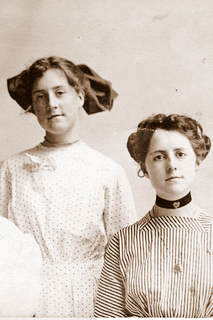 |
Bartholomew Thomas M. Treahy was born in July, 1866 in Woodstock, Oxford County, Ontario. He was the younger son of Patrick Joseph Treahy and Eliza Thomas Treahy. His brother was John Patrick Treahy. He was listed in the 1871 Ontario Census as age five. Bartholomew (Bartholamu) appeared in the 1881 census of Ontario. He was living with his mother, Eliza. He was a jeweller (sic) and his religion was Roman Catholic. Later he worked for his uncle, who owned the Thomas Organ Company. On June 18,1888 a note appeared in the Woodstock Sentinel Review that “Bert Treahy traveler for the Thomas Organ Company returned from his Nova Scotia trip" and on September 1, 1888 he returned from his Eastern trip.He married Marie des Neiges Robitaille on February 13, 1889 in Québec. She was born in July 1866. Her parents were Francoise Robitaille and Emilie Seboury.
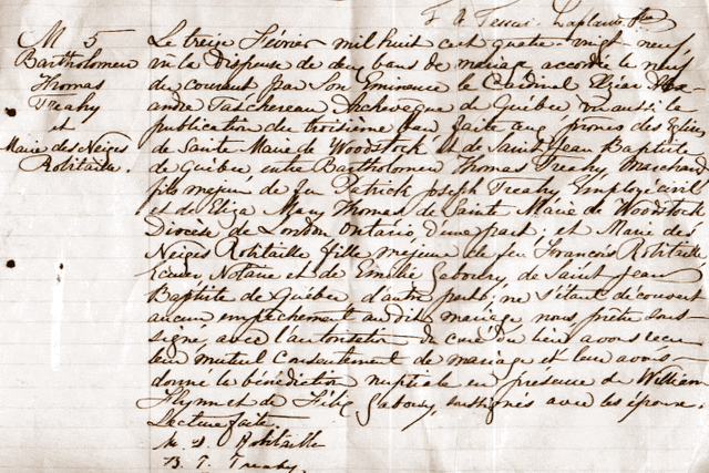 Marriage record for Bartholomew and Marie click to enlarge On September 25, 1891 he “left on a trip to the Eastern Provinces" according to the Woodstock Sentinel Review. At the time of the 1891 census they were living in Woodstock and Marie's mother was living with them. Their first four children were born in Canada. Albert Edward Treahy was born in November 24, 1889, Wilbur Joseph Treahy was born in December, 1890. Earl Grover Treahy was born in October 1892 and Alma.D. Treahy Perry was born in July, 1893. They moved to Michigan about 1894. Marie C. Treahy was born in April, 1895 and Corinne I. Treahy Shaull in 1896.  March 16, 1900, Detroit The family was listed in the 1900 census in Michigan. Bartholomew was the head of household. His birthdate was recorded as July, 1866 and he gave his age as 33. He had been married for 11 years. He listed his place of birth as Canada, his father’s as Ireland and his mother’s as Canada. The family came to the United States in 1895. His occupation then was piano-maker. He could read, write and speak English. Albert E. was born in November, 1889 and was ten years old. Wilber J. was born in December, 1890 and was 9 years old. Earl was born in October 1892 and was 7. Alma D. in July, 1893 and was six. Marie C. was born in April, 1895 and was five. At the time of the 1910 census they were still living in Detroit. The household consisted of Bartholow age 43, Desnique age 42, Albert E. age 20, Wilbur age 19, Alma age 16, and Corinne age 15. Bart and Albert were piano makers and Wilbur repaired bicycles. In 1930 Marie D. Treahy was living in Ubly, Huron County, Michigan with her daughter Alma’s family. 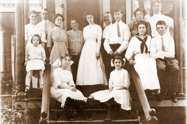 Standing: Jessie Treahy, Roy Mc Leary, Alma Treahy, Marie Treahy, Martha, Lucy Covert, Bartholomew Treahy, Wilbur Treahy, Florence Covert, George Saunders Sitting down: Irene Covert, Corinne Treahy, Nettie Covert, Lillie Treahy, Bert Treahy Albert Edward Treahy was born in November 24, 1889 in Woodstock, Oxford County, Ontario, Canada. He was the son of Bartholomew Treahy and Marie Desneiges Robitaille. According to the 1910 census, he was a piano maker like his father. He married Lucy Covert Treahy Cunningham. They did not have children. Lucy was born on June 26, 1895 in New York. Her parents were Frank Covert and Helen Wilhelmina Winter. Lucy’s siblings were Florence, Frank, Nettie and Irene. After his death she married John B. Cunningham. John was born on August 13, 1897. This was his second marriage. His first wife was Theresa Sweeney who was born on October 11, 1903. Albert died on June 17, 1950. Lucy died on June 11, 1965 in Detroit, Wayne County, Michigan. Wilbur Joseph Treahy was born on December 2, 1890 in Woodstock, Ontario, Canada. He was 19 at the time of the 1910 census and repaired bicycles.At the time of the 1930 census he was still living in Detroit. He was married to 37 year old Albertina Marie Marker. She was born in Michigan about 1892. He owned a bicycle company. Earl Grover Treahy was born October 6, 1892 in Canada. He died on October 20, 1907 when he was only 15 years old of a brain tumor. Alma D. Treahy Perry was born in July, 1893 in Canada. She married Charles E. Perry. He was born about 1881 in Canada. Their children were Ernest C. Perry (1918), and Alma Perry (1921). In 1930 they were living in Ubly, Huron County, Michigan. Marie C. Treahy was born in April, 1895 in Michigan.Corinne I. Treahy Shaull as born on April 30, 1896 in Michigan. She married Cleo Eugene Shaull on November 14, 1915. Cleo was born on September 22, 1893 in Gratiot County, Michigan. His parents were Anson Eugene Shaull and Mary E. Henrys.Their daughter Dorothy E. Shaull Fors was born in February, 1917. She married William A. Fors on October 25, 1940 and Their son Eugene Cleo Shaull was born on April 21, 1918 in Ingham County, Michigan. He married Kathleen Myers. Cleo died on September 16, 1893 in Michigan and Corinne died on August 13, 1997 in Michigan. |
|
||||
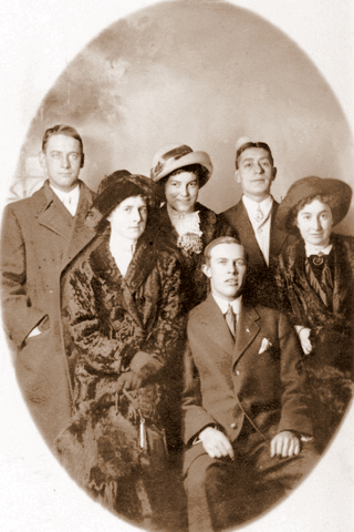 Postcard addressed to Mrs. L.W. Dobler Dear May, Pipe the hats and coats in this picture. It was snowing when we had this taken. Why don’t you write. Yours Sis, Lil |
||||||
Alma and Lillie's Detroit Visit Roy McLeary (?), Alma Treahy, Jessie Treahy, Wilbur Treahy (?), Lillie Treahy, Bert Treahy (?) |
||||||
|
||||||
|
||||||
|
||||||
|
©Roberta Tuller 2025
|
||||||